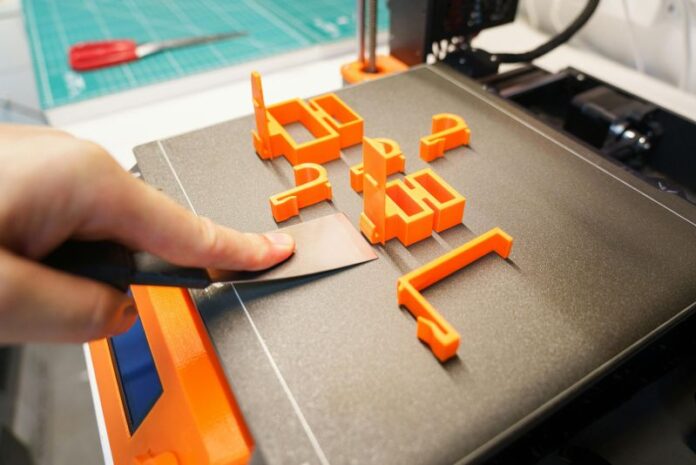
A modern 3D printer can have an almost ridiculous number of settings.
Open a slicer for the first time and you might see options for:
- Layer height
- Wall thickness
- Infill
- Supports
- Retraction
- Temperature
- Cooling
- Print speed
- Acceleration
- Travel
- Brim
- Raft
- Flow
- Top layers
- Bottom layers
- Seam position
- Overhangs
- And dozens of other options
It can be a little overwhelming.
The good news is that you don’t need to understand every setting to produce good 3D prints.
A handful of settings have a particularly large effect on print quality, strength, appearance and printing time.
This guide explains the most important ones in plain English, including what they do, when to change them and what happens when you push them too far.
First: What Does a Slicer Actually Do?
Before looking at individual settings, it helps to understand what the slicer is doing.
Your CAD program creates a 3D model.
The slicer takes that model and turns it into instructions the printer can follow.
It effectively answers questions such as:
Where should the nozzle move?
How much filament should it extrude?
How hot should the nozzle be?
Where should the printer slow down?
Where should supports be placed?
How many walls should the part have?
How much infill should go inside?
The slicer then produces printer instructions, commonly called G-code.
Think of the process like this:
CAD model → Slicer → G-code → 3D printer → Finished part
The slicer is where most of the settings in this article live.
1. Layer Height
Layer height is one of the most important 3D printing settings.
It determines how tall each individual printed layer is.
For example:
- 0.10 mm = very fine layers
- 0.20 mm = common general-purpose setting
- 0.30 mm = thicker, faster layers
Imagine building a wall out of very thin slices.
The thinner the slices, the more closely the printed object can approximate curved surfaces.
Smaller layer height
Generally gives:
- Smoother curved surfaces
- More detail
- Less visible layer lines
- Longer print times
Larger layer height
Generally gives:
- Faster printing
- More visible layer lines
- Less fine detail
- Potentially rougher surfaces
A practical starting point
For a typical 0.4 mm nozzle, 0.20 mm is a useful general-purpose starting point on many printers.
You might use:
0.12 mm for detailed models.
0.20 mm for everyday parts.
0.28 mm for faster prototypes.
These are examples rather than universal rules.
Your printer and nozzle determine what layer heights are practical.
2. Nozzle Diameter
Nozzle diameter has a major influence on what your printer can produce.
A common nozzle is:
0.4 mm
But you can also find:
- 0.2 mm
- 0.25 mm
- 0.6 mm
- 0.8 mm
- 1.0 mm and larger
Smaller nozzle
Useful for:
- Fine details
- Small text
- Tiny features
- Detailed models
But printing can take longer.
Larger nozzle
Useful for:
- Faster printing
- Large objects
- Stronger-looking walls
- Large functional components
A larger nozzle can deposit more material per unit time.
It can also allow you to use thicker layers and wider extrusion lines.
Important
Changing the physical nozzle means you need to tell the slicer about the new nozzle.
Don’t install a 0.6 mm nozzle and continue using a 0.4 mm nozzle profile.
3. Wall Count
Wall count determines how many outer perimeter lines the printer creates around the inside of the model.
You may see this setting called:
- Wall count
- Perimeters
- Shells
- Wall loops
Suppose you have a hollow box.
The outside isn’t simply one line of plastic.
The slicer can create several concentric walls.
More walls generally mean:
- Stronger parts
- Thicker outer surfaces
- Better resistance to damage
- More material
- Longer print times
Fewer walls generally mean:
- Faster printing
- Less material
- Thinner shells
For functional parts, increasing wall count can often be more useful than simply increasing infill.
4. Wall Thickness
Wall thickness is closely related to wall count.
Instead of thinking only in terms of “three walls,” you can think about the actual thickness of the shell surrounding the part.
For example, with a 0.4 mm nozzle, a slicer may produce wall lines around a fraction of a millimetre wide or wider depending on the extrusion settings.
The exact relationship isn’t simply:
0.4 mm nozzle = 0.4 mm wall
The slicer can use different line widths.
For functional parts, think about the required wall thickness rather than simply choosing the highest possible wall count.
5. Infill
Infill is the material printed inside the outer walls of a part.
A 3D printed object doesn’t normally need to be completely solid.
Instead, the slicer can create a lightweight internal structure.
You might see settings such as:
- 10%
- 15%
- 20%
- 30%
- 50%
- 100%
These represent the approximate density of the internal structure.
Low infill
Good for:
- Decorative objects
- Lightweight parts
- Large models
- Prototypes
Medium infill
Good for:
- General functional parts
- Brackets
- Enclosures
- Everyday components
High infill
Useful when:
- Extra internal support is required
- The part experiences significant loads
- The geometry benefits from a denser interior
But 100% infill isn’t automatically the strongest solution.
In many cases, more walls and an appropriate part orientation can provide a better strength-to-weight ratio.
6. Infill Pattern
Infill isn’t just a simple grid.
Your slicer may offer patterns such as:
- Grid
- Lines
- Gyroid
- Triangles
- Cubic
- Honeycomb
- Concentric
- Other specialised patterns
Different patterns provide different combinations of:
- Strength
- Weight
- Print time
- Material usage
- Internal support
Gyroid
Gyroid infill has become popular because it provides a continuous, complex internal structure and can produce a good balance of strength, material usage and appearance.
Grid
Simple and practical.
Lines
Can be fast and efficient for many applications.
Honeycomb
Visually interesting and can provide useful structural properties.
Don’t get too obsessed with finding the “best” infill pattern.
For most everyday printing, infill percentage, wall structure, material and orientation are usually more important than the difference between two reasonable infill patterns.
7. Top Layers
Top layers form the upper surface of your print.
If you have too few top layers, you may see:
- Gaps
- Holes
- Infill showing through
- Rough surfaces
Increasing top layers can improve the appearance and strength of the top surface.
Instead of thinking only about the number of layers, also think about top thickness.
For example, if your layer height is 0.2 mm:
5 top layers = approximately 1 mm of top-layer thickness.
10 top layers = approximately 2 mm.
This is why changing layer height can affect how many layers you need.
8. Bottom Layers
Bottom layers form the foundation of the printed object.
They provide:
- A strong base
- Better surface appearance
- Additional support
- A transition between the build plate and the main structure
If the bottom surface is poor, check your first-layer calibration before simply increasing bottom layers.
More layers won’t necessarily fix a badly calibrated Z-offset.
9. Supports
Supports are temporary structures printed underneath or around parts of the model that would otherwise be difficult or impossible to print.
Imagine trying to print a horizontal shelf in mid-air.
The printer can’t simply deposit plastic into empty space indefinitely.
Supports give it something to build on.
Supports are useful for:
- Overhangs
- Bridges that are too long
- Horizontal features
- Complex geometry
- Some curved structures
But supports have disadvantages.
They:
- Use extra material
- Increase print time
- Leave marks
- Need to be removed
- Can sometimes damage surfaces
The golden rule
Use as little support as necessary.
Before adding supports, consider whether you can simply rotate the model.
A different orientation can sometimes eliminate most of the supports.
10. Support Density
Support density controls how much material is used inside the support structure.
Higher density generally means:
- More support
- More material
- Better structural support
- More difficult removal in some cases
Lower density means:
- Less material
- Faster printing
- Easier removal
- Potentially less reliable support
Don’t automatically use extremely dense supports.
Modern slicers can often produce surprisingly effective support structures with relatively little material.
11. Support Interface
The support interface is the portion of the support structure directly underneath the printed model.
It can be designed to provide a more consistent surface for the model to print against.
This can improve the quality of supported surfaces.
However, if the interface is too close or too dense, removing the supports can become difficult.
This is a setting worth adjusting when you’re getting:
“The support worked, but I can’t get it off.”
12. Support Overhang Angle
Many slicers have a setting controlling when supports are generated.
This is often expressed as an angle.
For example, the slicer might be configured to support surfaces beyond a particular overhang threshold.
The exact angle that works depends on:
- Printer
- Material
- Cooling
- Layer height
- Print speed
- Geometry
Don’t assume there is one universal “maximum overhang angle.”
Instead, test your printer.
You may discover that your setup can print certain overhangs successfully without supports.
13. Brim
A brim is a series of extra lines printed around the base of the model.
It increases the area attached to the build plate.
Brims are particularly useful for:
- Tall narrow models
- Parts with small footprints
- Materials prone to warping
- Prints where additional adhesion is desirable
The brim is normally removed after printing.
It’s one of the easiest ways to improve print stability without changing the actual model.
14. Raft
A raft is a larger temporary platform printed underneath the model.
The model is then printed on top of that platform.
Rafts can be useful in certain situations, but they consume more material and take longer than a simple first layer or brim.
Modern build surfaces often make rafts unnecessary for many prints.
Use one when you have a specific reason.
15. Skirt
A skirt is printed around the model without necessarily touching it.
It doesn’t normally provide structural support.
Instead, it can be used to:
- Prime the nozzle
- Confirm filament is flowing
- Check first-layer height
- Check build-plate conditions
A skirt is therefore a very useful little diagnostic tool.
You get to watch the printer establish the first layer before it begins the actual model.
16. Print Speed
Print speed controls how quickly the printer moves while creating the model.
But there isn’t simply one “print speed.”
Different parts of a print can use different speeds.
Your slicer may have separate settings for:
- Outer walls
- Inner walls
- Infill
- Top surfaces
- Bottom surfaces
- Supports
- Bridges
- First layer
- Travel moves
Faster isn’t always better
Increasing speed can:
- Reduce print time
- Increase vibration
- Reduce surface quality
- Increase extrusion requirements
- Make cooling more difficult
- Reduce reliability
A good printer profile balances speed and quality.
17. Outer Wall Speed
Outer walls are often printed more slowly than internal features.
Why?
Because the outer wall is the part everyone sees.
If the printer vibrates or moves too aggressively, surface imperfections become visible.
Slowing the outer wall can therefore improve appearance.
For a functional prototype, you might accept a rougher surface in exchange for speed.
For a product prototype or presentation model, surface quality might be more important.
18. Infill Speed
Infill is usually less visible than the outer walls.
That means it can often be printed faster.
A common strategy is:
Slow down for appearance, speed up for hidden structure.
Your slicer may therefore use different speeds for walls and infill.
This allows you to reduce print time without sacrificing as much visible quality.
19. Travel Speed
Travel speed controls how quickly the print head moves when it isn’t actively depositing material.
Fast travel can reduce print time.
It can also reduce the amount of time the nozzle spends travelling between features, potentially helping with some stringing situations.
However, excessively aggressive movement can create:
- Vibration
- Ringing
- Mechanical noise
- Missed steps on some machines
Use the printer’s capabilities as your guide.
20. Temperature
Temperature is one of the most important settings in the entire slicer.
There are usually at least two temperatures to think about:
Nozzle temperature
Controls how hot the filament becomes.
Bed temperature
Controls the temperature of the build surface.
The correct values depend on the material.
For example:
PLA ≠ PETG ≠ ABS ≠ ASA ≠ Nylon ≠ TPU
Each behaves differently.
Temperature affects:
- Layer adhesion
- Stringing
- Bridging
- Surface quality
- Flow
- Warping
- Strength
This is why a temperature tower is such a useful calibration tool.
21. Part Cooling
Part cooling fans help solidify newly deposited plastic.
Cooling is particularly important for:
- Bridges
- Overhangs
- Small details
- PLA
But more cooling isn’t automatically better.
Some materials benefit from reduced cooling because excessive cooling can weaken layer bonding or contribute to warping.
Follow the material’s recommended approach and then fine-tune it for your printer.
22. Retraction
Retraction temporarily pulls filament backwards when the nozzle travels without printing.
Its purpose is to reduce unwanted oozing.
Without appropriate retraction, you may see:
Stringing
Too much retraction can cause:
- Grinding
- Clogging
- Inconsistent extrusion
- Delayed extrusion
Retraction settings depend heavily on the extruder design.
A direct-drive printer and Bowden printer can require very different settings.
23. Seam Position
Every layer has to begin and end somewhere.
That creates a seam.
The slicer may give you options such as:
- Aligned seam
- Nearest seam
- Random seam
- User-selected seam
- Back seam
- Corner seam
If your model has a visible vertical line, it may simply be the Z seam.
For a box, you might place it on the back.
For a cylindrical decorative object, you may choose a less visible location.
24. Horizontal Expansion
Horizontal expansion allows you to compensate for certain dimensional differences in the XY plane.
For example, if printed holes consistently come out slightly too small, a suitable compensation setting may help.
However, don’t use this setting as a substitute for proper calibration.
Before adjusting it, make sure:
- Extrusion is calibrated.
- Flow is reasonable.
- The nozzle is correct.
- The model is designed correctly.
- The material is behaving consistently.
Then use dimensional tests to determine whether compensation is actually necessary.
25. Layer Width / Line Width
Line width determines approximately how wide an individual extrusion line is.
It can be different from the physical nozzle diameter.
For example, a 0.4 mm nozzle may be used with a line width somewhat larger than 0.4 mm.
Wider lines can potentially provide:
- Faster material deposition
- Stronger-looking walls
- Good layer bonding
Narrower lines can help with:
- Fine details
- Small features
The slicer may automatically vary line width depending on the feature being printed.
26. Flow
Flow determines how much filament is extruded relative to the slicer’s calculated requirement.
You might also see this called:
Extrusion multiplier
A flow value that’s too high can cause:
- Bulging
- Excess material
- Poor dimensions
- Rough surfaces
Too low can cause:
- Gaps
- Weak walls
- Under-extrusion
Flow should generally be calibrated rather than randomly adjusted.
27. Layer Height vs Nozzle Size
These two settings are related.
A larger nozzle generally allows larger layer heights and wider extrusion lines.
A smaller nozzle allows finer detail.
As a rough conceptual guide:
Small nozzle + small layer height = detail
Large nozzle + larger layer height = speed
But you don’t need to use the smallest nozzle available to get good prints.
For everyday printing, a 0.4 mm nozzle remains a useful compromise between detail and productivity.
28. First Layer Settings
The first layer deserves special attention because it determines whether the entire print has a solid foundation.
Settings that can affect it include:
- First-layer height
- First-layer speed
- First-layer temperature
- First-layer line width
- Bed temperature
- Z-offset
- Initial cooling
A slightly slower first layer can often improve reliability.
And if your first layer is failing, don’t immediately change advanced settings.
Check the basics first.
29. Adaptive or Variable Layer Height
Some slicers allow the layer height to change throughout the print.
Instead of printing every layer at exactly 0.20 mm, the slicer might use:
- Thicker layers on simple vertical surfaces
- Thinner layers around curved or detailed areas
This can provide a useful balance between:
Speed + surface quality
It’s particularly interesting for models with both large simple areas and detailed curves.
30. Acceleration
Acceleration determines how quickly the print head changes speed.
High acceleration can make printing faster.
But excessive acceleration can produce:
- Ringing
- Ghosting
- Vibration
- Mechanical noise
- Reduced surface quality
If your printer produces repeated echoes around sharp corners, acceleration is one setting worth investigating.
Choosing Settings for Different Types of Prints
The easiest way to understand slicer settings is to think about what you’re trying to make.
Decorative Model
Priorities:
- Surface quality
- Fine detail
- Supports
- Seam visibility
Consider:
- Smaller layer height
- Moderate speed
- Appropriate supports
- Good temperature
- Lower visible-wall speed
Functional Bracket
Priorities:
- Strength
- Dimensional accuracy
- Layer adhesion
- Reliable printing
Consider:
- Appropriate wall count
- Moderate infill
- Correct orientation
- Good layer bonding
- Appropriate material
Don’t automatically use 100% infill.
Fast Prototype
Priorities:
- Speed
- Reasonable accuracy
- Low material usage
Consider:
- Larger layer height
- Larger nozzle
- Lower infill
- Fewer supports
- Faster internal printing
You don’t need a beautiful print if you’re only checking whether the design fits.
Outdoor Part
Priorities:
- Material suitability
- Strength
- Weather resistance
- Dimensional stability
Consider the material first.
For example, ASA may be more appropriate than PLA for some outdoor applications because of its resistance to UV and weathering.
How Settings Affect One Another
One of the most important things to understand is that slicer settings don’t operate independently.
Changing one setting can affect several others.
For example:
Increase layer height
You may get:
- Faster printing
- More visible layers
- Different overhang behaviour
- Different support requirements
Increase print speed
You may need to consider:
- Temperature
- Extrusion capacity
- Cooling
- Acceleration
Increase nozzle size
You may need to reconsider:
- Layer height
- Line width
- Flow
- Print speed
- Detail settings
Increase infill
You get:
- More material
- Longer print time
- More internal structure
But you may not get a proportional increase in strength.
This is why 3D printing is a system rather than a collection of independent switches.
A Beginner’s General-Purpose Profile
If you’re new to 3D printing, don’t start by modifying dozens of settings.
A better strategy is:
Start with your printer manufacturer’s profile.
Then use:
- A sensible layer height
- Recommended filament temperature
- Recommended bed temperature
- Moderate print speed
- Standard wall count
- Moderate infill
- Automatic or sensible supports
- Standard retraction
- Manufacturer-recommended cooling
Print something simple.
Then adjust only the setting that addresses the problem you actually see.
This is much easier than trying to create the perfect profile from scratch.
A Useful Setting Strategy
When you’re deciding whether to change a setting, ask:
Do I need better quality?
Try:
- Smaller layer height
- Slower outer walls
- Better temperature
- Better cooling
- Better orientation
Do I need more strength?
Try:
- More walls
- Appropriate infill
- Better orientation
- Better layer bonding
- Stronger material
Do I need faster printing?
Try:
- Larger layer height
- Larger nozzle
- Faster infill
- Fewer supports
- Lower infill where appropriate
Do I need better dimensional accuracy?
Check:
- Calibration
- Flow
- First layer
- Material behaviour
- Tolerances
- Horizontal compensation
Do I need fewer supports?
Try:
- Rotating the model
- Changing its orientation
- Redesigning overhangs
- Adjusting support thresholds
The Settings You Should Learn First
If the slicer still feels overwhelming, start with these:
Essential
- Layer height
- Nozzle diameter
- Wall count
- Infill percentage
- Infill pattern
- Top and bottom layers
- Supports
- Print temperature
- Bed temperature
- Print speed
Learn next
- Retraction
- Cooling
- First-layer settings
- Brim and skirt
- Flow
- Line width
- Seam position
Advanced
- Acceleration
- Pressure/flow compensation systems
- Advanced support settings
- Variable layer height
- Dimensional compensation
- Advanced motion settings
You don’t need to master all 23 before you start printing.
Learn them as you encounter situations where they become useful.
A Simple Print-Setting Cheat Sheet
| Setting | What It Controls | Increase It For | Decrease It For |
|---|---|---|---|
| Layer height | Layer thickness | Speed | Detail |
| Wall count | Number of outer walls | Strength | Material/time savings |
| Infill | Internal structure | More internal support | Lightweight parts |
| Top layers | Top surface thickness | Better top surfaces | Faster prints |
| Bottom layers | Bottom thickness | More base structure | Faster prints |
| Support density | Support structure | More support | Easier/faster prints |
| Print speed | Movement while printing | Faster production | Quality/reliability |
| Temperature | Filament melting | Better flow/layer bonding if too cold | Less oozing if too hot |
| Retraction | Pullback during travel | Reduce stringing | Reduce clogging risk if excessive |
| Cooling | Solidification | Overhangs/bridges | Layer bonding for some materials |
| Brim | Build-plate contact | Adhesion/stability | Easier cleanup |
| Flow | Material amount | Fix under-extrusion if verified | Fix over-extrusion if verified |
| Line width | Extrusion width | Deposition/strength | Fine detail |
| Acceleration | Speed changes | Faster motion | Less vibration |
Don’t Chase the Perfect Profile
There is a tendency among 3D-printing enthusiasts to endlessly tweak settings.
You can spend hours adjusting a value from 0.95 to 0.97 and wondering whether the print looks better.
Sometimes it does.
Sometimes it doesn’t matter at all.
Remember what the printer is for.
If you’re producing useful parts reliably, you’ve already achieved something important.
A slightly visible seam isn’t necessarily a problem.
A few layer lines aren’t necessarily a problem.
A print taking ten minutes longer isn’t necessarily a problem.
The best settings are the ones that give you the right combination of quality, strength, speed, reliability and cost for the job.
Final Thoughts
3D printer settings can look complicated because modern slicers give you enormous control over the printing process.
But you don’t need to learn everything at once.
Start with the big decisions:
Layer height → walls → infill → supports → temperature → speed.
Then gradually learn the settings that solve specific problems.
If you want more detail, learn retraction.
If you’re getting poor bridges, learn cooling and bridge settings.
If parts don’t fit, learn flow and dimensional calibration.
If prints are taking too long, investigate layer height, nozzle size, speed and infill.
And if you’re trying to improve strength, don’t simply turn infill to 100%. Think about walls, material, orientation and layer bonding.
The real skill in 3D printing isn’t knowing what every setting does.
It’s knowing which setting to change, why you’re changing it, and what you expect the change to accomplish.
Once you understand that, the slicer stops looking like a wall of mysterious numbers and starts becoming what it really is:
A control panel for turning a digital model into a physical object.

